
\[ \]
\[ \]
\[ \]
Issue No 21, 27 March 2023
By: Anthony O. Ives
For RC aircraft electric motors have advanced a lot particularly with the introduction of brushless motors. Electric powered RC aircraft can achieve the same performance that previously would only have been possible with aircraft powered by internal combustion (IC) engines. A lot of the inprovement in performance of electric powered vehicles in general is due to the high power lithium batteries [1] however, brushless motors have also improved the efficiency. Brushed motors generally generate more losses especially when the carbon brushes wear down however, brushless motors require a more complicated and hence expensive speed controller (ESC).
A brushed motor is more correctly a DC (Direct Current) motor whereas a brushless motor is more correctly an AC (Alternating Current) motor. Both are based on the principle that an electric wire with a current flowing through it placed in a magnetic field will generate a force. In a DC motor the magnets are fixed and the coil rotates. In the case of a DC motor the carbon brush is needed to create a path for the electric current. The current must flow through the coil in the correct direction when it aligned with magnet, so the carbon brushes which are know as commutors achieve this mechanically [2]. An idealised diagram of a DC motor is given below:
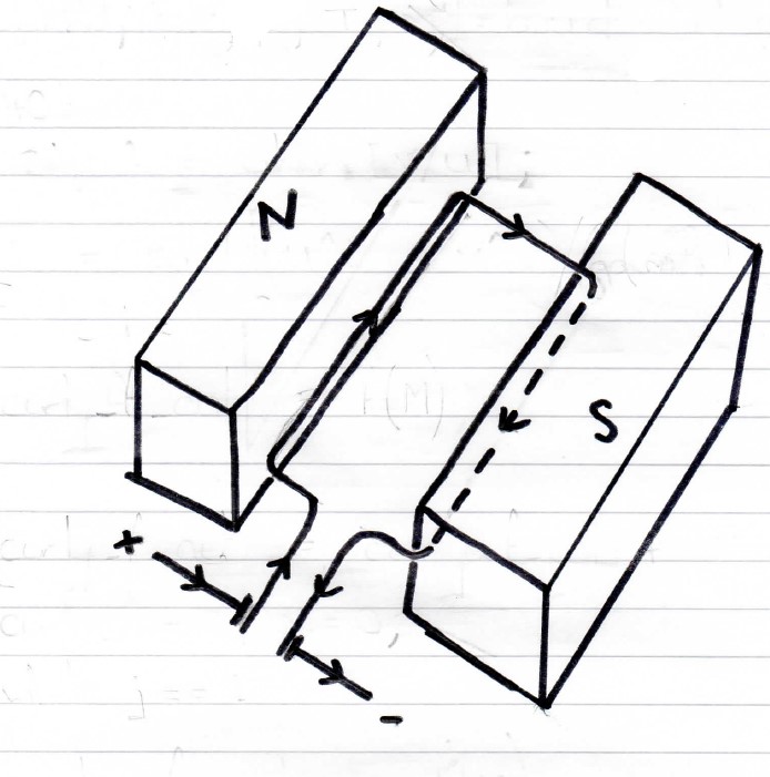
The equation below gives the total torque produced by the electric motors in general, where T is torque, IA is current in the coil, b is coil breath, L is coil length and N is the number of turns in the coil. B is magnetic flux density typically assumed to be 0.35 Tesla for permanent magnets.
T = BIALbN
The equations below give the motor's angular speed, where ωmotor is the motor angular speed, RA is the coil resistance, V is voltage and k=NAB. Where A=Lb and T is Torque.
\[V - k \omega_{motor} = \left( \frac{T}{k} R_A \right) \]
\[\omega_{motor} = \frac{1}{k} \left( V - \frac{T}{k} R_A \right) \]
These equations are quite simplistic, and more complicated ones exist depending on how the magnetic field is generated whether it is using a permanent magnet or an electromagnet.
A direct current flows in the same direction around the circuit with constant magnitude however, an alternating current is changing direction and magnitude with time usually in the form of a sin wave. The equations defining alternating current variation with time are as follows:
\[V(t) = V_{peak} sin \omega t\]
\[I(t) = I_{peak} sin \omega t\]
Where t is time, ω is the angular frequency of the current flow, Vpeak is the maximum voltage, Ipeak is maximum current. A DC motor mush fed by a direct current to function correctly whereas an AC motor must be fed by alternating current to function correctly. The below picture shows various types of electric motors including both brushed (DC) and brushless (AC) motors.
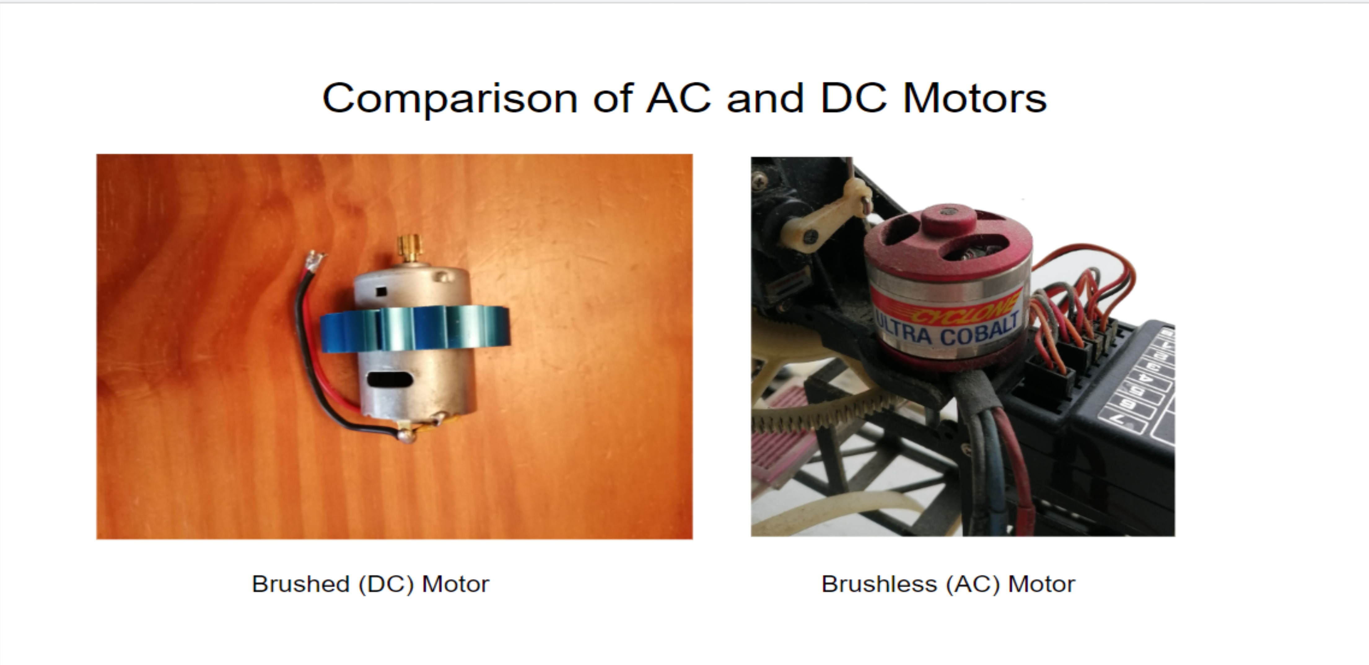
In a brushless/AC motor the magnets spin whereas the electric coil is fixed hence the alternating current angular frequency must choosen so that current flows in the correct direction when the coil wires are aligned with the magnet. This is why brushless/AC motors require a more complicated speed controller. Batteries produce direct current so the speed controller for a brushless/AC motor must contain extra electronics to convert the direct current to alternating current these electronics are referred to as an inverter. The inverter will probably have to vary the angular frequency of the current with speed controller's control of the motor's speed. The speed controller usually controls the motor's speed by varying the current supply. Some brushless motors have sensors that detect the position of the magnets so that the correct alternating current is used by the speed controller however most brushless motors used by RC aircraft do not have sensors.
A speed controller for a DC motor is fairly simple Ref [3] actually tells you how to build one. Electric motor are quite complex especially AC motors this article just serves to give a basic introduction to them and discuss the basic princples. Electric motors are used in the servo systems as well so also are needed to make flight and automatic flight possible [4].
Please leave a comment on my facebook page or via email and let me know if you found this blog article useful and if you would like to see more on this topic. Most of my blog articles are on:
Mathematics
Helicopters
VTOL UAVs (RC Helicopters)
Sailing and Sailboat Design
If there is one or more of these topics that you are specifically interested in please also let me know in your comments this will help me to write blog articles that are more helpful.
References:
[1] http://www.eiteog.com/EiteogBLOG/No18EiteogBlogBattery.html
[2] Hughes Electric Technology, Edward Hughes, 7th Edition, 1995, Prentice Hall
[3] Electronic Projects for Model Aircraft, Ken Ginn, 1998, Nexus Special Interests
[4] http://www.eiteog.com/EiteogBLOG/No14EiteogBlogRC.html
![]()


Disclaimer: Eiteog makes every effort to provide information which is as accurate as possible. Eiteog will not be responsible for any liability, loss or risk incurred as a result of the use and application of information on its website or in its products. None of the information on Eiteog's website or in its products supersedes any information contained in documents or procedures issued by relevant aviation authorities, manufacturers, flight schools or the operators of aircraft, UAVs.
For any inquires contact: [email protected] copyright © Eiteog 2023