
\[ \]
\[ \]
\[ \]
Issue No 14, 2 January 2023
By: Anthony O. Ives
Radio Controlled (RC) model airplanes and helicopters are usually controlled by linkages to the control surfaces or swash plate respectively. The control linkage is moved by a servo, the servos are all connected to a radio receiver. The receiver receives control signal from transmitter. The RC transmitter usually has two control sticks which the operator uses to maneuver the aircraft if control is manual however modern commercial UAVs can also use automatic control. Both the transmitter and reciever need a power source such as a battery.
The essential components of a RC system is:
Transmitter/Controller
Reciever
Servo Mechanisms
The first thing to start explaining is the transmitter or controlling unit typically used on manually controlled RC model aircraft. Your typical RC transmitter has two control sticks, the one on the left controls rudder (yaw) and throttle, and the right one controls elevator (pitch) and aileron (roll). This is a mode 1 transmitter for a mode 2 transmitter the control sticks are reversed hence the throttle stick is on the right. The throttle stick is the only one that is not spring loaded to center obviously so you can hold a desired throttle setting. The picture below shows a typical 35 MHz mode 1 RC transmitter :
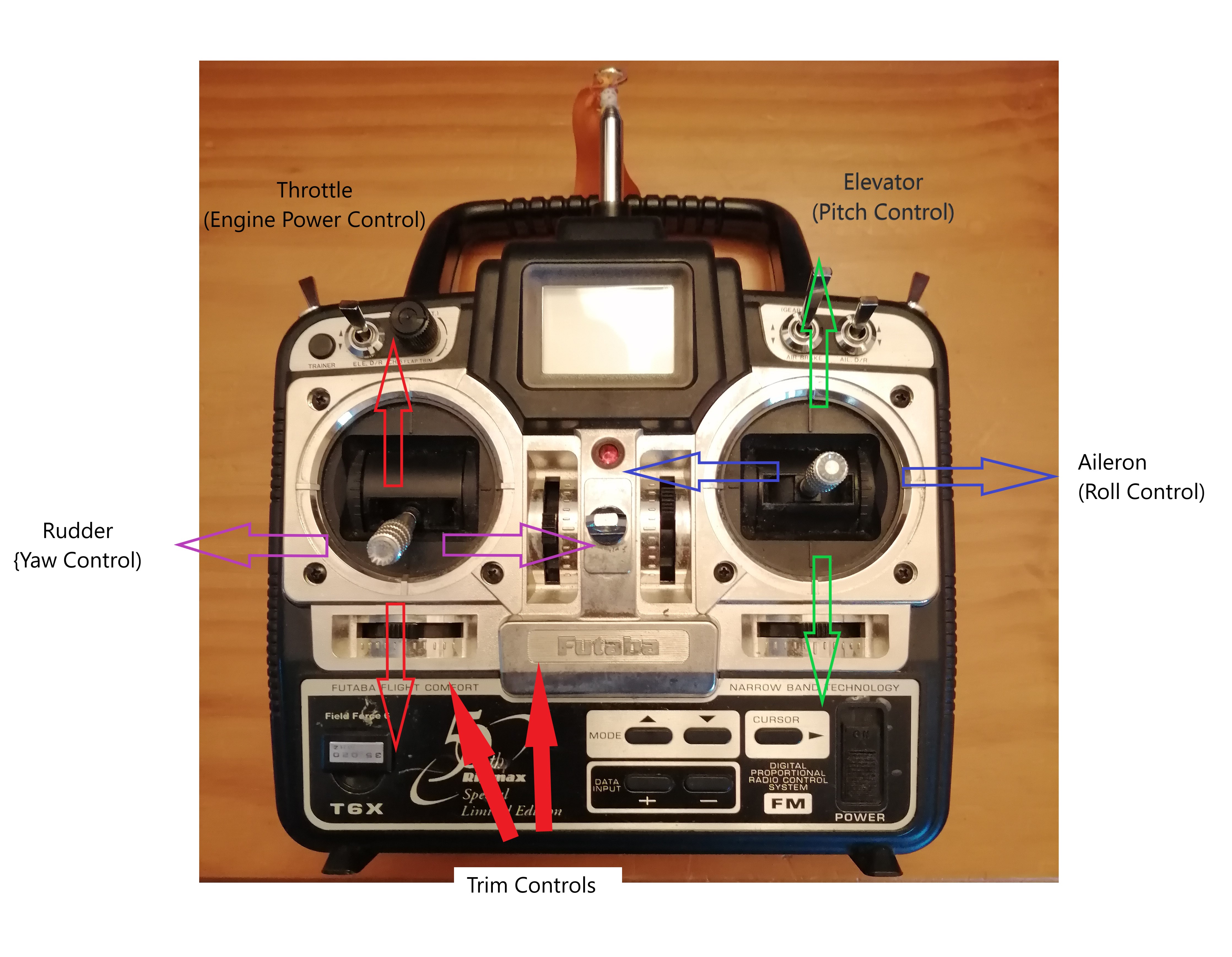
For a RC model airplane you would at need least a 4 channel transmitter because each control requires a channel e.g. aileron, elevator, throttle and rudder. However, most RC transmitters have 6 channels, with extra channels used for switches to lower landing gear or control flaps or some other secondary system. Early and inexpensive RC transmitters are limited on how you could customise them as each control only controlled one servo maybe two if you use a y connector. For example some airplanes require a bit of rudder as well as aileron to make them bank. You could obviously control both servos using aileron control by connecting both rudder servo and aileron servo to the aileron channel via a y connector. However, this gives some problems first you will not be able to control the rudder independently especially during take off when you need to and secondly you may not want the rudder servo to move at the same rate as the aileron servo. One possible way around this was to use a mechanical mixing device installed in the aircraft and connect it to both servos and both control surfaces. Mechanical mixer devices have disadvantages such as adding extra weight, taking up extra space and can be frustrating, time consuming to set up. Modern computerised transmitters allow you to program each control to control multiple specific servos at different rates allowing you to easily setup the aileron-rudder mixing described above but also other mixing needed for V tails or delta wings. Usually the transmitter has build in typical mixing functions but you may able to create you own custom ones as well. Some RC Helicopters need mixing I will discuss this in more detail in a later article. Earlier transmitters were 35 MHz or 72 MHz usually recreational model flying clubs would need some sort of frequency designation system or board so that two people would not accidentally operate on the same frequency. Modern transmitters use 2.4 GHz which have higher variety of frequencies hence can make use of frequency hopping reducing the possibility of interference. The antennae has also reduced in size this is because the antenna needs to be half the size of the wavelength and higher frequencies have lower wavelengths as per the formula below:
\[c_0 =f \lambda \]
Where c0 is the speed of light (3 × 10⁸ ms-1) as radio waves travel at the speed of light. f is frequency in hertz (Hz) and λ is wavelength in metres (m).
\[ \lambda =\frac{c_0} {f}\]
\[ \lambda =\frac{3 \times 10^8} {35 \times 10^6} = 8.571m\]
\[ \lambda =\frac{3 \times 10^8} {2.4 \times 10^9} = 0.125m\]
2.4 GHz transmitter will look similar to a 35 MHz one with exception a 2.4 GHz system does not need the long extendable antenna. Transmitters are probably the most complicated piece of equipment in a basic RC system. Depending on how much you want spend RC transmitters can be as sophisticated as you want and include as many channels as you need if you want to control secondary systems on your RC aircraft.
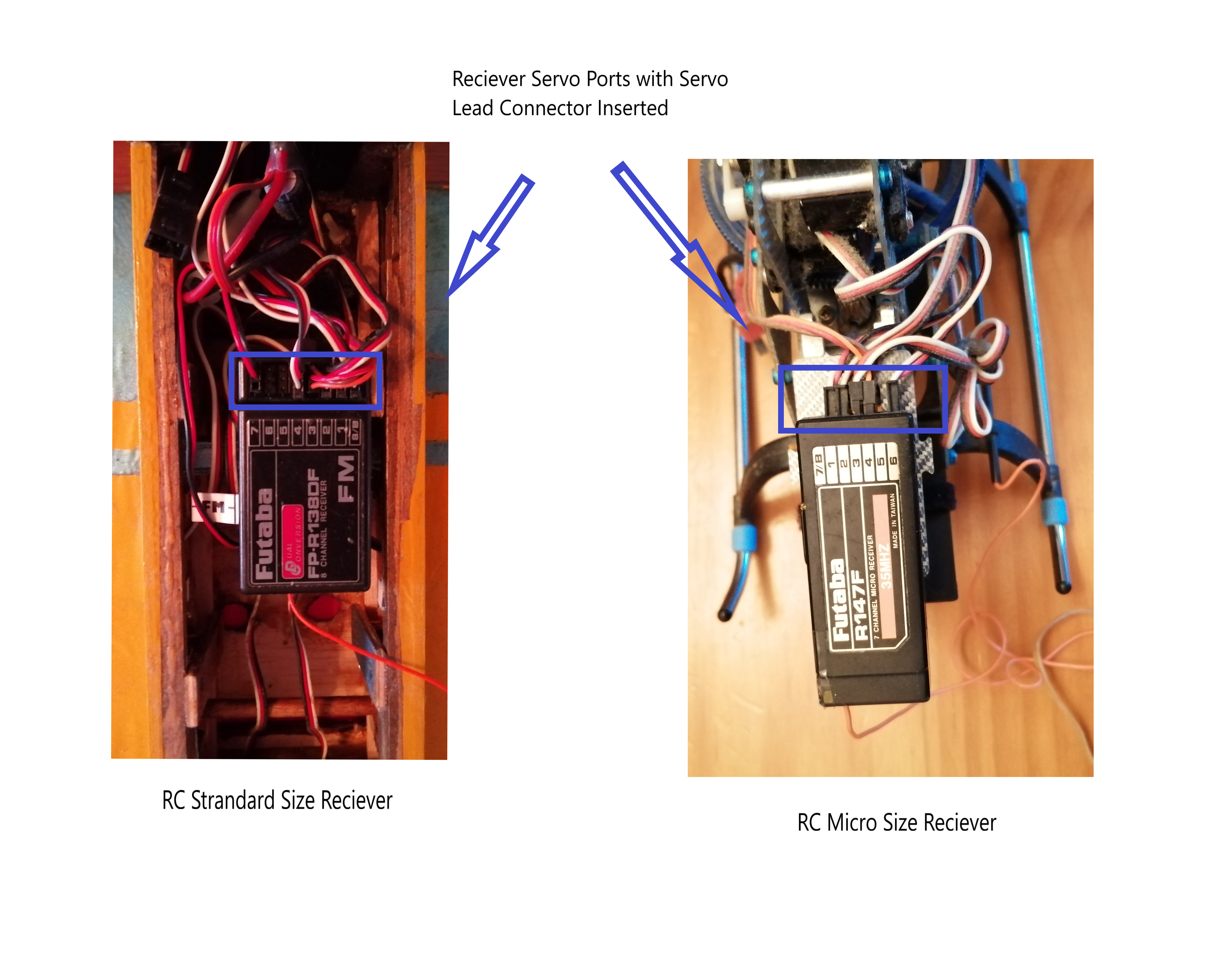
The next piece of equipment is the receiver, the receiver receives the control signals from the transmitter which then distributes them to the correct servos. Receivers have ports to plug the servo leads in to. Typical port designations are as follows:
Channel 1 - Aileron (Roll Control)
Channel 2 - Elevator (Pitch Control)
Channel 3 - Throttle (Power Control)
Channel 4 - Rudder (Yaw Control)
Channels 5 and onwards are used for auxiliary controls sometimes channel 6 can also be used for aileron control if there is some sort of mixing function being used. As with transmitter antennae receiver antennae has also reduced in size due to the introduction 2.4GHz radio systems. There is not much more to explain about receivers they really are just a box of electronics for the radio signal reception, processing and distribution to the servos. The figure below shows a typical 35MHz receiver a 2.4 GHz receiver will look similar with a smaller antenna.
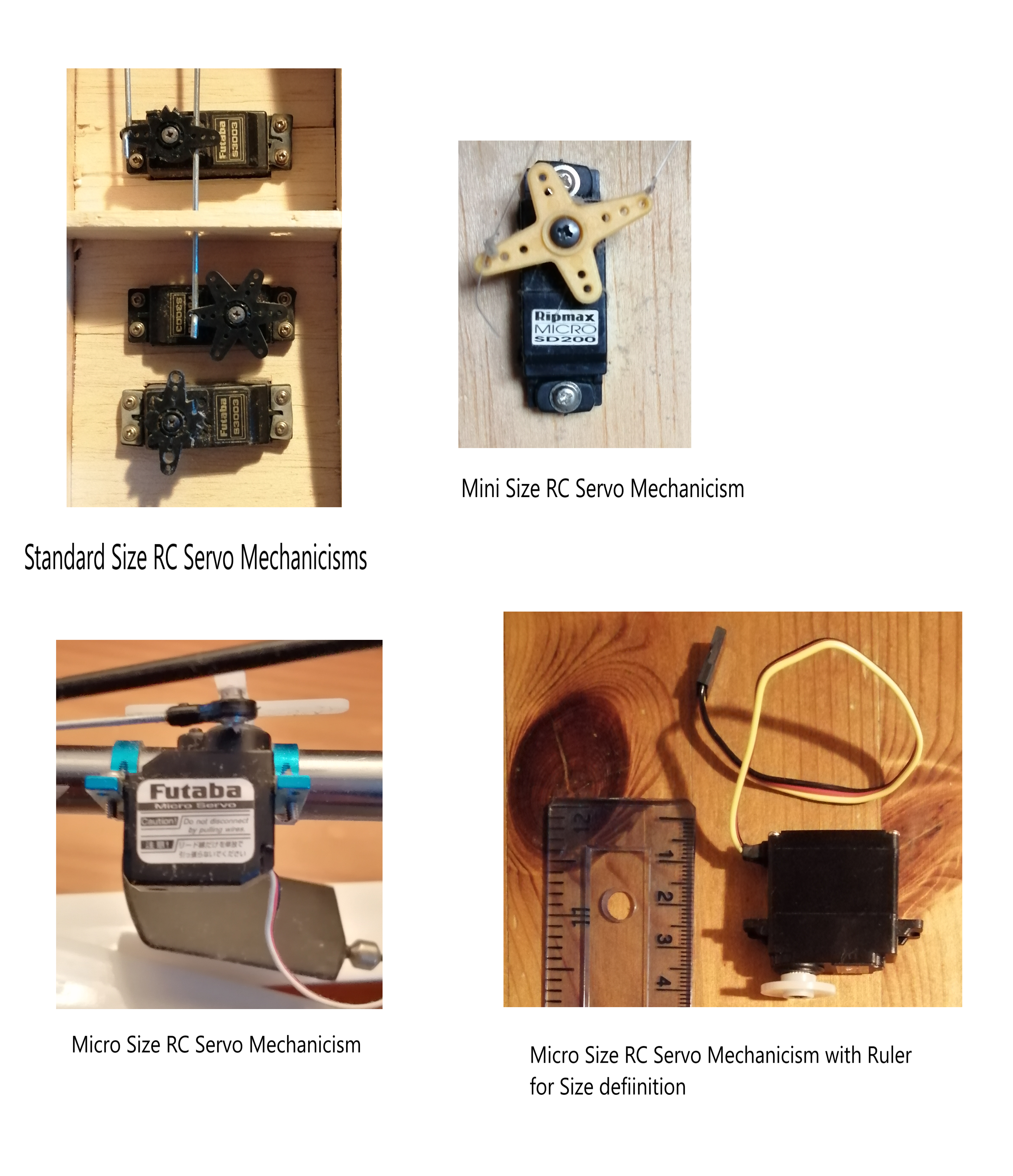
Servo mechanisms usually just referred to as servos are what converts the control signal into a mechanical movement which moves the relevant control surface. In RC model aircraft the servo mechanism consists of some electronics, and electric motor and a set of gears all inside a box with the rotating head protruding. Servos can come in a variety of sizes as well as a variety of performance. Average sized model aircraft would use standard size servos with average specifications. Smaller aircraft can use micro or mini servos. You can also get high powered servos for things like landing gear retract systems. Helicopters may use high specification servos specifically for tail rotor pitch control. High specification servos may use gear systems made of metal instead of plastic, brushless motors instead brushed motors as well as more sophisticated electronics to increase performance. Generally what type of servo specification you use depends on the application of the RC aircraft for example aircraft performing extreme maneuvers will probably require high specification servos to avoid them failing. Below contains a picture of a variety of servo mechanisms installed in a variety of RC aircraft:
There is a variety of other RC equipment such as gyros, battery monitors and other novelty items but I will discuss these in future articles, this article is just to introduce the basic essential RC equipment. A good understanding of general electronics is very helpful when using RC systems or if you are innovative enough to try build your own novelty items, something like Ref [1] is a very useful reference for helping you understand electronic principles. Ref [2] discusses different RC electronics that you can create yourself including even servo splitter plate electronics, the book is slightly dated but is still relevant if you want to understand more about RC electronics and a good introduction about how you go about building you own specialised RC electronics. Speed controllers are used on electric powered RC aircraft, they come with a servo lead which you plug into the throttle channel port on the reciever. Internal Combustion (IC) engine powered aircraft would use a servo and linkages to open and close the throttle arm on the engine in same way the control surfaces are operated.
The SMART check is something I learned when learning to fly RC aircraft, the 'A' however was to remind you to extend antennae on 35 MHz systems which is not really revelant for 2.4 GHz systems maybe you can think of something different to use 'A' to remember?
S - Switch on, make sure the transmitter and especially the receiver is switched on before letting the aircraft take off
M - Meter in the green, make sure the transmitter power meter is in the green, it is also a good idea to have a power meter installed on the aircraft for the receiver battery as well, essentially check that you radio systems have enough battery power
A - Aerial extended, very important for 35MHz systems because you will soon lose control after take off if your aerial is not extended but not relevant for 2.4GHz systems
R - Rate switchs set correctly, these are switches on your transmitter which control how much your control surfaces move if they are set incorrectly you could have too little or too much control movement
T - Trim controls set correctly, these are knobs on your transmitter for each control they are set so the aircraft flies as close to steady level flight as possible when the control sticks are centered, for example if your aircraft tends to pitch up with the controls centred you can add some elevator down trim to stop it
Failsafe transmitter and reciever combinations are something that can be used to reduce fatal or serious consequences if interference causes loss of control of your RC aircraft. Failsafe systems are usually associated with PCM (Pulse Code Modulation) receivers, they can be programmed to carry out a set commands if the receiver loses signal from the transmitter, a common one would be to reduce engine or motor power. The receiver is usually programmed through the transmitter however you should carefully read the instructions of your radio system, its always a good idea to set up as many safety features as you can as even small RC aircraft can cause serious and fatal accidents. Bearing mind that RC aircraft can be dangerous its a good idea to generally follow all safety recommendations in any documentation with the RC equipment. Most countries have model flying associations which will advise you on the best safety practices and can also offer insurance as part their memberships and a simpler registration process with the relevant aviation authority if your country requires one. Typical associations are Academy of Model Aeronautics (AMA) which is the US official national body for model aviation and probably the biggest one in the world, others that I know of are Model Aeronautics Council of Ireland (MACI) and the British Model Flying Association (BMFA). These type of associations only apply to recreational model flying if you are flying UAVs for commercial reasons you may need to licensed by the aviation authority for your country and maybe also need private insurance. Insurance is always good idea but the larger and heavier your model aircraft or UAV becomes the more necessary it is.
Modern UAV systems carrying out military and commercial operations can operate completely autonomously which means just using an on-board autopilot with no or little interaction from a ground controller. This has a big advantage in military operations where the enemy would deliberately try to cause radio interference usually referred to as jamming but it also makes commercial operations safer too. Artificial Intelligence (AI) can also be used in modern UAV systems. AI is really just a software program which tries to copy how a human reasons and decides on a course of action, the definition of AI has changed through time for example thermostats were once considered AI but not anymore. I hope this article has been helpful to you and remember to carefully read the documentation for your RC systems as it may differ from some of generalisations I have given here.
Please leave a comment on my facebook page or via email and let me know if you found this blog article useful and if you would like to see more on this topic. Most of my blog articles are on:
Mathematics
Helicopters
VTOL UAVs (RC Helicopters)
Sailing and Sailboat Design
If there is one or more of these topics that you are specifically interested in please also let me know in your comments this will help me to write blog articles that are more helpful.
References:
[1] Electronic Circuits Fundamentals and Applications, Mike Tooley, 3rd Edition, 2006, Newnes-Elsevier
[2] Electronic Projects for Model Aircraft, Ken Ginn, 1998, Nexus Special Interests
![]()


Disclaimer: Eiteog makes every effort to provide information which is as accurate as possible. Eiteog will not be responsible for any liability, loss or risk incurred as a result of the use and application of information on its website or in its products. None of the information on Eiteog's website or in its products supersedes any information contained in documents or procedures issued by relevant aviation authorities, manufacturers, flight schools or the operators of aircraft, UAVs.
For any inquires contact: [email protected] copyright © Eiteog 2022