
\[ \]
\[ \]
\[ \]
Issue No 29, 29 May 2023
By: Anthony O. Ives
There are many ways of defining drag such lift dependent drag, profile drag, form drag, wave drag, etc. However, I always find it easier to remember drag by the typical things that cause drag such skin friction, separated flow, lift induced trailing vortices and shock waves for high speed flow. In this article I will discussing drag caused by mainly skin friction and separated flow. In future articles I will discuss drag caused lift induced trailing vortices and shock waves. For helicopters shock waves are not really a major concern apart from in rotor tip region where the flow can approach the speed of sound. Apart from shock waves most drag is caused by friction or viscosity maybe just not directly and as obviously usually because the process through which friction losses occur are induced by either separated or lift producing flow.
To summarise, drag is usually caused by one of the four:
Skin Friction
Separated Flow (Can be referred to as Form Drag or Pressure Drag)
Trailing Vortices induced by Lift producing flow
Shock Waves (Referred to as Wave Drag)
In reality lift producing flow can cause additional skin friction drag, separated flow drag and shock wave drag just because it changes how the airflow behaves so drag classed as lift dependent drag is usually the result of more than trailing vortices.
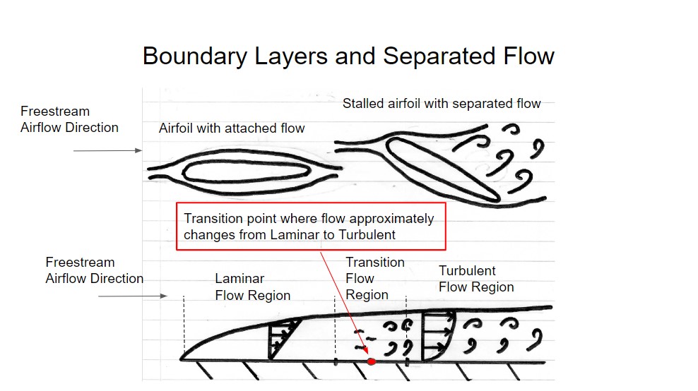
Skin friction drag is the result of a thin layer of the airflow moving close to a surface in which viscosity has a dominant effect. This layer of airflow is called a boundary layer where the velocity of the airflow (often referred to as the freestream velocity) reduces through the thickness of the boundary layer to zero on the surface in contact with the airflow. There are two types of viscous flow, laminar flow and turbulent flow. Laminar flow is smooth orderly flow where as turbulent flow is disorderly flow with random fluctuations. Generally airflow at the leading edge of a surface where the surface first comes in contact with the airflow is laminar. As the airflow progresses along the surface it becomes more unstable and eventually becomes turbulent flow. The flow where laminar is changing to turbulent flow is often referred as transition flow with the aproximate point where flow becomes turbulent called the transition point. In reality the flow transitions over region and not at one point so it should be more correctly referred to as the transition region. Correspondly a boundary layer varies form laminar intially to a transition region to finally a fully turbulent region. The boundary layer flow will grow in thickness as it progresses along a surface but the thicker regions will still be relatively thin.
There are two equations for predicting drag for airflow across a flat plate, the first one is for laminar flow:
\[C_D=\frac{1.328}{\sqrt{Re_L}} \]
The one for turbulent flow is:
\[C_D=\frac{0.074}{Re_L^{\frac{1}{5}}} \]
Where CD is drag coefficient and ReL is Reynolds number which is defined as follows:
\[Re_L = \frac{\rho UL}{\mu} \]
Where L is the length of the flat plate, U is the airflow velocity, ρ is density and μ is dynamic viscosity usually 1.7 x10⁻⁷ Pas for air. A graph is given below for flat plate drag coefficient against Reynolds number in both the case of laminar and turbulent flow:
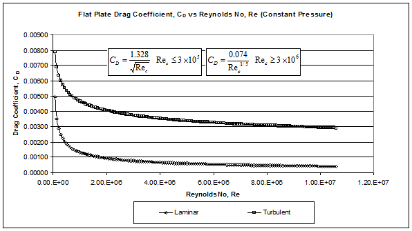
One question you may have is how do you determine if a flow is laminar or turbulent. Generally you do this from the Reynolds number for a Reynolds number less than 3.6 x10⁵ you assume laminar flow, if its greater than 3.6 x10⁶ then you assume turbulent flow. If its somewhere in between you could determine an average value from both laminar and turbulent values. In reality turbulent flow could occur for lower Reynolds depending on the surface the airflow is exposed to for example a rough surface or a bump, etc could cause the flow to become turbulent early. Likewise the flow could stay laminar for longer if the surface is exceptionally smooth but this is less likely although there is always people looking for ways of keeping airflow laminar around an aircraft, as this gives a lower drag coefficient as can seen in the graph above. In general skin friction is very small compared with other forms of drag although I will increase as the velocity of the aircraft increases.
Another way airflow can transition to turbulent flow earlier than expected is through separation of flow from the surface. Flow usually separates from a surface due to sudden change is profile where the flow suddenly deaccelerates. A good example of separated flow is when a aircraft wing stalls due to excessive angle of attack in this case it results in a loss of lift which is of course a hazardous flight condition for an aircraft. Separated flow produces lots of vortices, eddies which gives highly turbulent flow producing no lift but lots of drag. Separated flow is harder to predict generally aerodynamicist try to prevent it by designing surfaces which do not have unfavourable changes in profile. In modern times drag caused by separated airflow along with other aspects of separated flow is predicted using CFD (Computional Fluid Dynamics) which is a complex numerical method used to solve the governing equations of fluid dynamics. In a future article I hope to do a formal introduction to CFD.
The are other terms you may come across that are used to describe different types of drag [1]. For example profile drag or parasite drag is used to refer to drag which is not result of lift hence zero lift drag. Zero lift drag has generally been the topic of this article. Form drag or pressure drag are also terms used to refer what I would call separation drag, the reason it is referred to as pressure drag is because the separation flow usually creates pressure suction forces. Wave drag is a term used to refer to drag caused by shock waves, it can sometimes be included under the definition of form drag or pressure drag. In future articles I will discuss drag caused by lift induced trailing vortices and shock waves. The diagram below illustrates separated flow, boundary layers, laminar and turbulent flows:
In a previous article [2] the drag polar equation was introduced as given below:
\[C_D = C_{D0} + k C_L^2\]
Where CD is total drag coefficient, CL is lift coefficient and k is the drag factor. CD0 is the zero lift drag coefficient which has been the topic of most this article which is mainly caused by skin friction and separated flow. The drag factor, k is mainly the result of trailing vortex drag induced by a lifting airflow pattern, but as I said earlier the lifting airflow can also cause additional skin friction and flow separation so this may need to be taken account in the value of the drag factor as well as the trailing vortex.
Please leave a comment on my facebook page or via email and let me know if you found this blog article useful and if you would like to see more on this topic. Most of my blog articles are on:
Mathematics
Helicopters
VTOL UAVs (RC Helicopters)
Sailing and Sailboat Design
If there is one or more of these topics that you are specifically interested in please also let me know in your comments this will help me to write blog articles that are more helpful.
References:
[1] Fundamentals of Aerodynamics, John D. Anderson Jr., 3rd Edition, 2001, McGraw Hill
[2] http://www.eiteog.com/EiteogBLOG/No2EiteogBlogDragCD.html
![]()


Disclaimer: Eiteog makes every effort to provide information which is as accurate as possible. Eiteog will not be responsible for any liability, loss or risk incurred as a result of the use and application of information on its website or in its products. None of the information on Eiteog's website or in its products supersedes any information contained in documents or procedures issued by relevant aviation authorities, manufacturers, flight schools or the operators of aircraft, UAVs.
For any inquires contact: [email protected] copyright © Eiteog 2023