
\[ \]
\[ \]
\[ \]
Issue No 23, 17 April 2023
By: Anthony O. Ives
Airfoil lift generation has been explained in different ways with some explanations not being completely correct. However, sometimes a simplified explanation is helpful if it makes it easier to remember a important concept this is particular true if you are learning the princples of flight for pilot training. Lift generation is not really easy to explain, in reality airfoils produce a vortex which then generates circulation around the airfoil. The circulation around the airfoil slows the airfoil on the lower surface of the airfoil while causing high speed airflow on the upper surface. These differences in airfoil speeds on the upper and lower also produces a pressure difference between upper and lower surface which cause the airfoil to lift this principle is described by the bernoulli equation. The equation for lift equation is derived from vortex theory as in shown in most aerodynamics books [1].
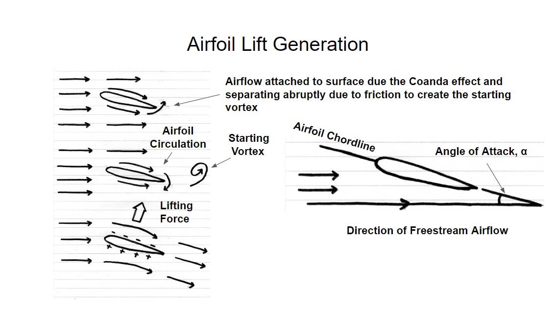
An airfoil starts producing lift as result of the following process:
As forward airflow starts moving around the airfoil, airflow at the trailing edge of the airfoil begins to turn upwards as result of friction forces.
This upwards airflow at the trailing edge causes the airflow to spin and become a vortex. This vortex is known as a starting vortex.
This starting vortex generates a similar type of vortex action around the airfoil due Newton's third law. Newton's third law states that to every action there is an opposite and equal reaction.
The reaction to the starting vortex does not generate a complete vortex, the forward airflow prevents this happening at the airflow surface and instead it just slows the airflow at the airfoil lower surface and accelerates the airflow at the airfoil upper surface. This is known as circulation around the airfoil.
As a result of the principle defined by the bernoulli equation, high speed airflow gives a low pressure and low speed airflow gives a high pressure, this produces the upwards lifting force.
The diagram below gives a graphical description of lift generation:
The bernoulli equation is given below:
\[p_{upper} + \frac{1}{2} \rho U_{upper}^2 = p_{lower} + \frac{1}{2} \rho U_{lower}^2\]
\[p_{lower} - p_{upper} = \frac{1}{2} \rho \left( U_{upper}^2 - U_{lower}^2 \right)\]
Where pupper is the pressure on the upper surface, plower is the pressure on the lower surface, Uupper is the velocity on the upper surface, Ulower is the velocity on the lower surface and ρ is the air density.
Coanda effect is sometimes used to describe airfoil lift generation. The coanda effect is the tendency of airflow to attach to a surface. The coanda effect explains how airflow stays attached to surface and the abrupt separation at the airfoil trailing edge that generates the starting vortex.
Airfoil lift generation is sometimes explained as result of the airfoil causing the airflow to turn. While the airflow will turn due the low pressure at the lower surface and the high pressure at upper surface it is probably too simple of an explanation. A starting vortex and circulation around the airfoil is really what generates lift, this is the way aerodynamic text books [1] explain lift generation and derive equations for lift coefficient, etc.
In a previous article lift coefficent was introduced [2] as a function of airflow velocity, air density, wing area and the lifting force. However, lift coefficent is also a separate function of airfoil angle of attack and airfoil geometry. This equation for lift coefficient is derived in aerodynamic text books [1] from the vortex theory described earlier in the article. The derivation is lengthly and complex using fourier equations and integration so this article will not go into that detail.
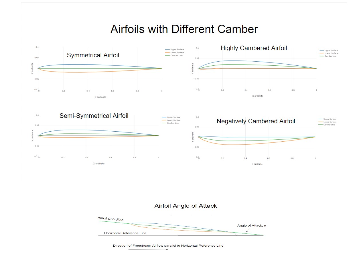
One of the most important features of airfoil geometry defining lift generation is the camber line. The camber line is a line that can be drawn through each mid point between upper and lower airflow surfaces. For symetrical airfoil geometry the camber line is straight. An important concept is that symetrical airfoil generates no lift at a zero angle of attack. Symetrical airfoils are used in rotor blades, propeller blades, tailplanes and tailfins, etc. If the airfoil has a camber line which is curved up (known as positive camber) it produces some lift at zero angle of attack the higher the curve the more lift it will produce at zero angle of attack. Cambered airfoils are used mainly in aircraft wings however some modern advanced helicopters are using them for their rotor blades. If the airfoil has a camber line which is curved down (known as negative camber) is produces some negative lift at zero angle of attack and similarly the lower the curve the more negative lift it will produce at zero angle of attack. Negative camber airfoils are used for specalised applications apparently early flying wing experiments (early experiments to test the B-2 Stealth Bomber concept) used negative camber airfoils.
The diagram below gives a illustration of the different types of airfoils:
The equation that is derived from vortex theory is actually quite simple even though the derivation process is complicated. The equation is given below:
\[C_L = a \left( \alpha + \beta \right) \]
Where α is the angle of attack in radians, CL is lift coefficient, β is angle which accounts for the airfoil camber it also must be in radians and 'a' is the lift curve slope. In theory the lift curve slope will be equal to 2π but in reality it will probably have a smaller value than this. β is the negative angle of attack that would be needed to give zero lift for a positive cambered airfoil. For a symmetrical airfoil β is zero. Generally speaking the more camber an airfoil has the larger the value of β. A negatively cambered airfoil will have positive angle of attack to produce no lift and β will be negative.
Angle of attack is defined as the angle between the airfoil chord line and the direction of freestream flow, it is shown graphically in both the diagrams given in this article.
Lift generation also generates a moment about the airfoil as the lift generated across an airfoil is not evenly distributed. The lift distribution is usually considered to act at a single point called center of pressure however this point can move around due to lift distribution changing typically with changes in angle of attack. So aerodynamic centre is a single point often referred to where lift distribution acts and assumes a constant moment about the airfoil to account for changes in center of pressure. In a future article I will discuss aerodynamic moments, center of pressure and aerodynamic center in more detail This article has introduced the basic principles of lift generation which has only considered steady effects. In reality lift generation can be unsteady in which the airfoil can be shredding vortices as angle of attack changes this is particularly true for helicopter rotor blades, I hope to introduce these concepts in future articles and discuss other topics such as stall considering the interesting case of dynamic stall which is particularly relevant to helicopters.
Please leave a comment on my facebook page or via email and let me know if you found this blog article useful and if you would like to see more on this topic. Most of my blog articles are on:
Mathematics
Helicopters
VTOL UAVs (RC Helicopters)
Sailing and Sailboat Design
If there is one or more of these topics that you are specifically interested in please also let me know in your comments this will help me to write blog articles that are more helpful.
References:
[1]Fundmentals of Aerodynamics, John D. Anderson Jr., 3rd Edition, 2001, McGraw Hill
[2] http://www.eiteog.com/EiteogBLOG/No1EiteogBlogLiftCL.html
![]()


Disclaimer: Eiteog makes every effort to provide information which is as accurate as possible. Eiteog will not be responsible for any liability, loss or risk incurred as a result of the use and application of information on its website or in its products. None of the information on Eiteog's website or in its products supersedes any information contained in documents or procedures issued by relevant aviation authorities, manufacturers, flight schools or the operators of aircraft, UAVs.
For any inquires contact: [email protected] copyright © Eiteog 2022