
\[ \]
\[ \]
\[ \]
Issue No 11, 14 November 2022
By: Anthony O. Ives
Thrust coefficient was introduced in Ref [1], in that blog article the thrust coefficient was defined in terms of lift coefficient. This article will introduce lift coefficient in terms of rotor blade pitch and rotor inflow ratio which can then be used to give thrust coefficient in terms of rotor blade pitch and rotor inflow. An equation can relate lift coefficient to an airfoil angle of attack (or incidence angle), the origin of this equation will be explained in more detail in a later article but for now we will just use it to understand the influence of inflow on rotor thrust. The lift coefficient can be defined as below:
CL=aα
Where a is the lift curve slope with a theoretical value of 2π and α is the airfoil angle of attack (or incidence angle). In reality a will be less than 2π you can determine it from experimental data like that given Ref [2]. The next equation defines α in terms of rotor blade pitch and rotor inflow. The diagram explains the angles associated with the rotor blade.
\[ \alpha =\theta_{.75} -\frac32 \lambda \]
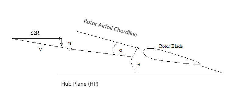
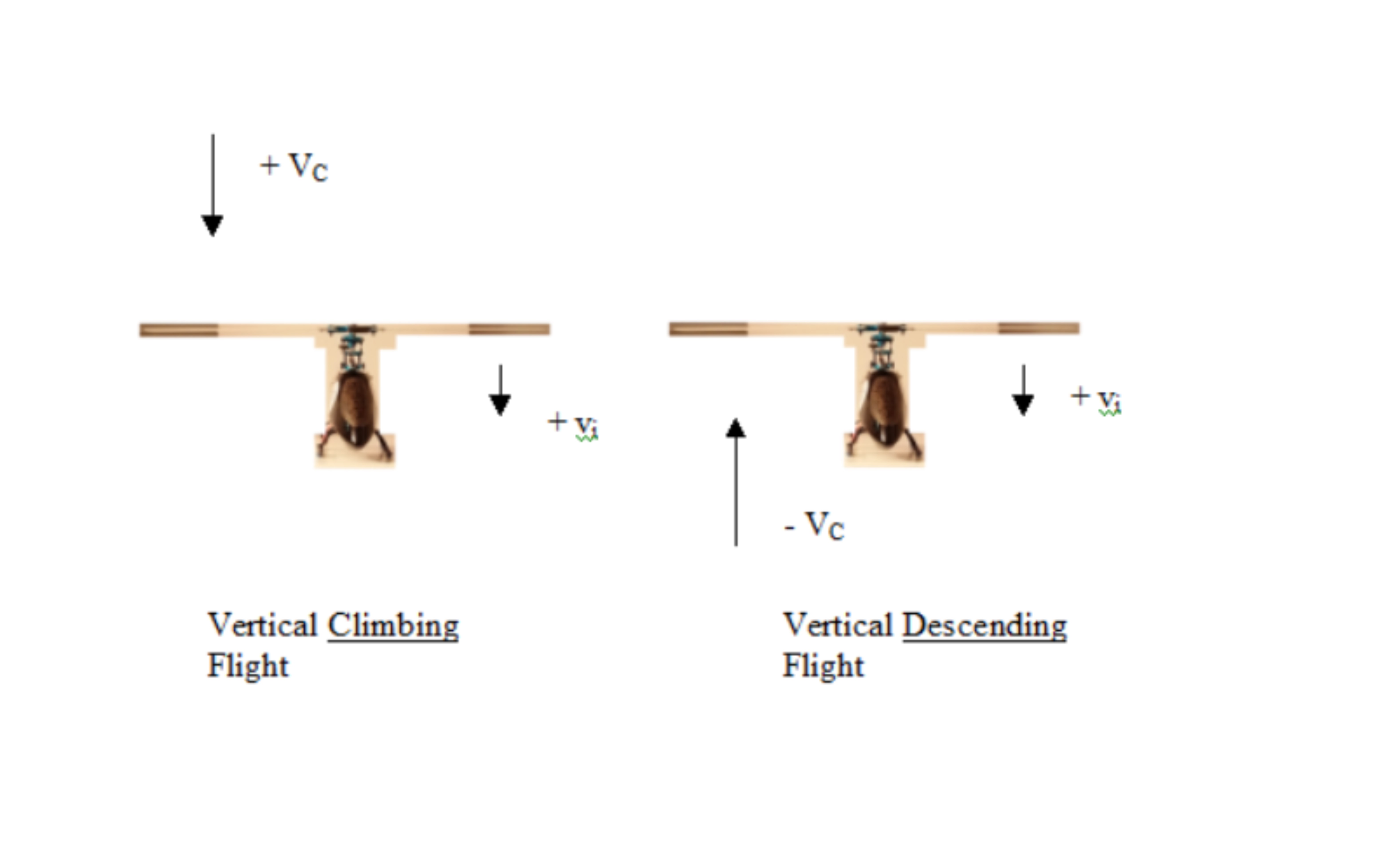
Where θ is rotor pitch angle and λ = (VC+vi)/ΩR is rotor inflow ratio, vi is inflow velocity, VC is climb velocity or rate, ΩR is the rotor tip velocity as defined in Ref [5]. The rotor tip velocity is reference speed used for all ratios and coefficients concerned with rotary wing aerodynamics. Rotor pitch angle is measured relative to rotor's hub path. Measuring rotor blade pitch especially for small RC helicopter is something that will be addressed in a later article but you are probably asking yourself what is inflow? Inflow is the velocity of an airflow produced by anything like propeller, helicopter rotor or desk fan. A desk fan increases the air from zero to the speed of the air that is cooling you down this is the same for helicopter hovering or airplane not moving on the apron or runway . Once an airplane is moving or helicopter is vertically climbing, inflow will increase from its stationary flow to include to airflow produced by the aircraft moving. Windmills, wind turbines and helicopters descending still produce an inflow it is just they are slowing down the airflow passing through their rotor. The inflow is generally considered positive while descent rates are considered negative, the same can assumed for windmills and wind turbines. The below diagram explains inflow for a helicopter:
Inflow actually varies across the rotor, and the rotor pitch can vary also as some twist may be designed in, this is the reason why the rotor pitch at 75% radius is used and the equation is also slightly more complex to take into consideration the variable inflow effects. In rotary wing aerodynamic equations the hover inflow is usually considered to be the reference inflow. From the equation for α you can see with increasing inflow hence forward speed or vertical climb rate α will reduce if θ is kept constant. This demonstrates the problem with fixed pitch propellers, in propeller or rotor with variable pitch or θ you can increase θ to compensate for the increase in inflow. So using the equations for lift coefficient, α and the equation given in Ref [1] you can get the following equation for thrust coefficient:
\[C_T=C_L\frac{\sigma}{6}=\frac{\sigma a}{2} \left( \frac{\theta_{.75}}{3} - \frac{\lambda}{2} \right) \]
There are four inflow states that apply to helicopters, propellers and wind turbines they are as follows:
Normal working state which includes hover.
Vortex ring state.
Turbulent wake state which realistically is the state for autorotation.
Windmill brake state.
The remainder of the article will explain each inflow state and the scenarios in which they are encountered, however this is just an introduction to the inflow states future articles will look at vortex ring, aurorotation and wind turbines in more detail.
Normal working state is how the helicopter performs when hovering and operating in powered climbing flight with no or very little forward speed. The only time this state does not apply is if the aircraft is descending vertically with no or very little forward speed. This state also applies to forward flight but is slightly more complex due to the forward airspeed component the following equations therefore only apply to hover or completely vertical climbing flight:
\[ \]
\[ \lambda = \frac{\lambda_C}{2} + \sqrt{\left( \frac{\lambda_C}{2} \right)^2+ \frac{C_T}{2}}\]λC=VC/ΩR. The above equation can be simplied if λC=0, or simply if the helicopter is hovering hence cimb rate is 0, therefore hover inflow ratio is:
\[ \lambda_h = \sqrt{ \frac{C_T}{2}}\]λh=vh/ΩR, where vh is the hover inflow.
Vortex ring state only applies if the helicopter is powered, descending at reasonable rate with little or no forward airspeed. If the helicopter is not under power then vortex ring state is not possible. This state can be very dangerous, a future article will look at it in more detail. The same inflow equation applies as in normal working state except λC is negative to indicate a descend rate as opposed to a climb rate.
Turbulent wake state is usual the state which applies to autorotation. Autorotation is an engine off condition which allows the helicopter to safely descend and land under control if the engine stops. The rotor does not act like a windmill in this state more like parachute or a bluff body. The inflow equation is similar to normal working state with exception of the inclusion of an a negative sign. λC is always negative to indicate a descend rate as opposed to a climb rate, as this state only applies to descend. Future articles will look at autorotation in more detail. See inflow equation for turbulent wake state below:
\[ \lambda = \frac{\lambda_C}{2} + \sqrt{\left( \frac{\lambda_C}{2} \right)^2- \frac{C_T}{2}}\]For windmill break state the rotor again is not powered but is behaving like a windmill or wind turbine. It is the only other state apart from normal working which has smooth flow both vortex ring and turbulent wake states are highly turbulent. Like normal working state the inflow equation predicts inflow rates more accurately than for vortex ring and turbulent wake states. The inflow equation is similar again except it has two negatives, again λC is always negative to indicate a descend rate as opposed to a climb rate, as this state also only applies to descend. See inflow equation for windmill break state below:
\[ \lambda = \frac{\lambda_C}{2} - \sqrt{\left( \frac{\lambda_C}{2} \right)^2- \frac{C_T}{2}}\]Future articles will also look at wind turbines in more detail hence considering windmill break state as a way of estimating wind turbine performance. Ref [4] looks at wind turbine performance in more detail.
The below graph plots inflow velocity ratio against climb velocity ratio using hover inflow as a reference:
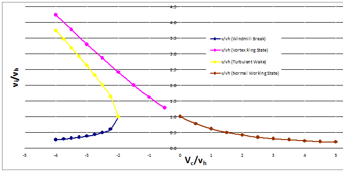
It is useful to note the following relationships:
\[\frac{v_i}{v_h} =\frac{\lambda-\lambda_C}{\lambda_h}\]
\[\frac{V_C}{v_h} =\frac{\lambda_C}{\lambda_h}\]
Determining whether you are in turbulent wake state or windmill break state is really the result of the rotor pitch angle, negative angles may give windmill break state while positive angles give turbulent wake state, hence why windmill break state does not always apply to helicopters in autorotation. Further information and full derivation of the equations in this article can be found in Ref [3].
I hope you have found this article helpful and now understand how inflow influences thrust coefficient, rotor blade angle of attack and choice of rotor pitch angle. You should understand the four different types of inflow state and when they occur.
Please leave a comment on my facebook page or via email and let me know if you understand how inflow affects rotor blade angle of attack.
References:
[1] http://www.eiteog.com/EiteogBLOG/No4EiteogBlogThrust.html
[2] Theory of Wing Sections: Including a Summary of Airfoil Data, Ira H. Abbott and A. E. Von Doenhoff, 1960, Dover Publications
[3] Helicopter Theory, Wayne Johnson, 1980, Dover Publications
[4] Wind Turbine Technology: Fundamental Concepts in Wind Turbine Engineering, 2nd Edition, David A. Spera, 2009, American Society of Mechanical Engineers, U. S.
[5] http://www.eiteog.com/EiteogBLOG/No10EiteogBlogCircle.html
![]()


Disclaimer: Eiteog makes every effort to provide information which is as accurate as possible. Eiteog will not be responsible for any liability, loss or risk incurred as a result of the use and application of information on its website or in its products. None of the information on Eiteog's website or in its products supersedes any information contained in documents or procedures issued by relevant aviation authorities, manufacturers, flight schools or the operators of aircraft, UAVs.
For any inquires contact: [email protected] copyright © Eiteog 2022